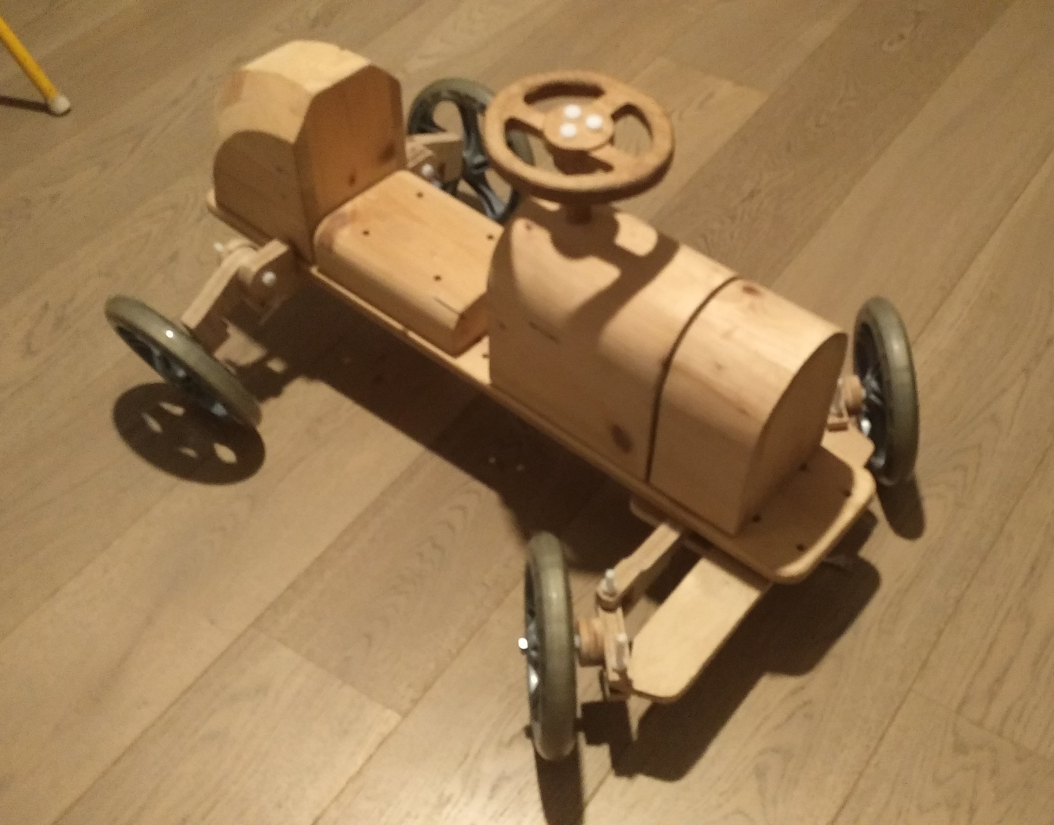
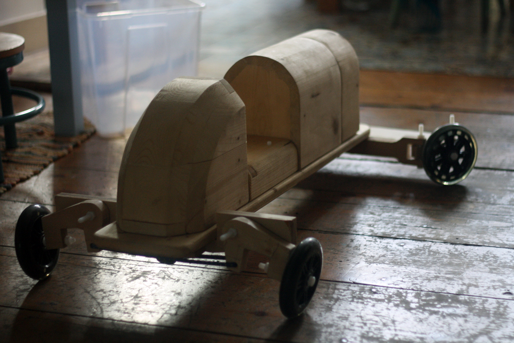
Designing a modular ride-on-car
A toy for daddy?
Ah, the joys of parenting. For example, as soon as I got used to the idea of a little one being dependant on me, I clamped on to the idea that a hand built toy car was required. The reasons were various, but mostly it was some sort of transition thing; a process for me to become a daddy. I know, I know, the diapers will be process aplenty.
After research I planned the car to be used as a ride on toy by the child from age 1 and adjusted up to age 4. Given the size of the thing and my love of all things modular, I also came up with the idea that from age 3 onwards the car would be used as a construction toy.
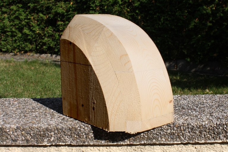
The modules are standardized. The smallest standard module is 20cm. wide, 30cm. high, and 10cm. deep, with a rounded (hemicylindrical) top.
The idea is that custom parts can be made and traded between diy-ers. So the car can get an exposed hotrod engine, different colors, an airplane tail, a boat front, etc.
This of course without losing track of the child's comfort and safety!
A stab at ergonomics.
The first and most important ergonomic question is the seat height. This changes as the child grows.
Age Seat Total
1 16cm 75cm
1.5 20cm 81cm
2.5 25cm 92cm
Obviously this stepped 10cm change would be easy to achieve solely by changing modules- but you'd have to replace every module twice, which struck me as wasteful.
It's easier to use two seperate systems, replacing first the wheels, then the seat. The starting seat would be 10cm high. After 6 months the wheels are changed from 10cm to 20cm high, putting the axle (and thus the seat)5cm higher.
Finally the seat is replaced achieving the final 5cm.
All modules are placed on a multiplex platform 2.5cm thick and attached via both wooden pins and a bolt. The bolt is there only to retain the modules when the car is picked up- it does not bear any weight. Thus I initially planned have the bolt be wooden. However the risk of too much (perhaps lateral) force snapping the bolt, leading to a module coming loose with a sharp splinter projecting, is not worth the ecological gain.
After a brief search I found nylon bolts to be the most child-friendly
Having different lengths of platform allows for different configurations of car, but is also essential to accommodate the child's longer legs and arms; both steering wheel and front wheels have to be placed further away from the seat.
Vacationing in the garage.
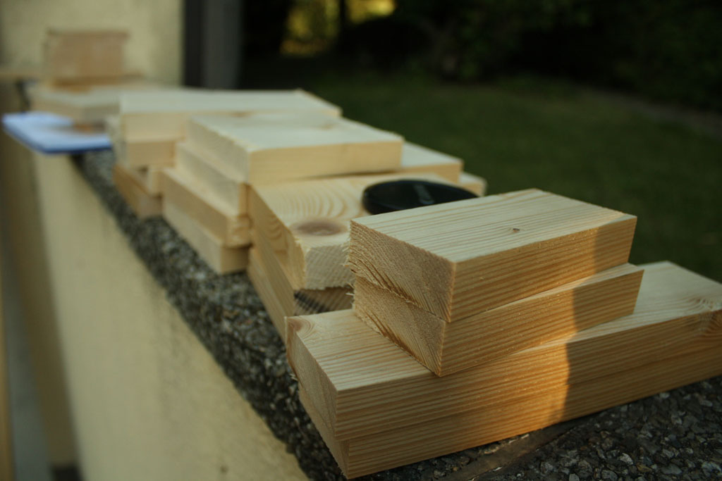
My SO and I were preparing to vacation at her parents' place in Austria. She mentioned the project to her dad and suggested we do it overthere. The man graciously accepted, and once we got there proved invaluable. The first step was to get the wood I needed at the local woodyard. Prices were, as expected, a lot less than in Brussels, but the choice was not much broader. For planks in 20mm I was restricted to several standard widths. I quicly re-calculated the modules for However on request the yard was more than happy to mill the wood down for us.
We picked the wood up a day later, for a mere 12 euro.
However on arrival back at the garage a few problems became apparent.
Something rotten in the state of NiederOsterrreich.
First of all we found the wood that was supposed to be 12cm was 11.4cm. Luckily I'd designed the car with such contingencies in mind, and there were only two pieces that needed to be adapted. But it put a damper on the first day.
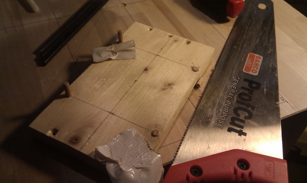
We went on to cut the 11.4cm plank, neglecting to check the angle of the cut. The saw was set at a right angle, right?
 Wrong.
But we continued with the 16cm wide planks. The problem was that the sawblade didn't reach the whole width. We tried turning the plank around, and that's when we discovered the problem.
The saw was 1 degree off. All of the wood would have to be re-cut. Instead we opted to correct the cuts later. In hindsight I really should have gotten a new plank at that point- the extra work it caused us doubled construction time.
The 16cm wide plank was cut by hand, with a clamped on piece of wood acting as a fence. Those cuts were near flawless.
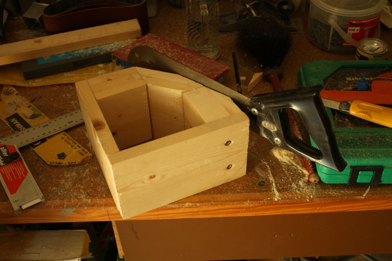
The second issue started as my SO's father suggested using dowels for the construction. I hadn't planned on it, but it would make the construction stronger. I didn't realize that, though I'd designed for certain cutting mistakes, the dowels would require zero tolerance exactitude. And we couldn't deliver.
The miscut pieces were a bit too short, and even the with of the pencil stripes I used to mark the drillholes- not to mention my own lack of accuracy meant the dowels would not fit. Worse, they would offset pieces and leave gaps between the wood.
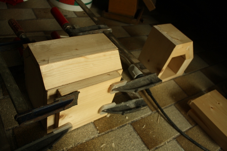
When the going gets tough...
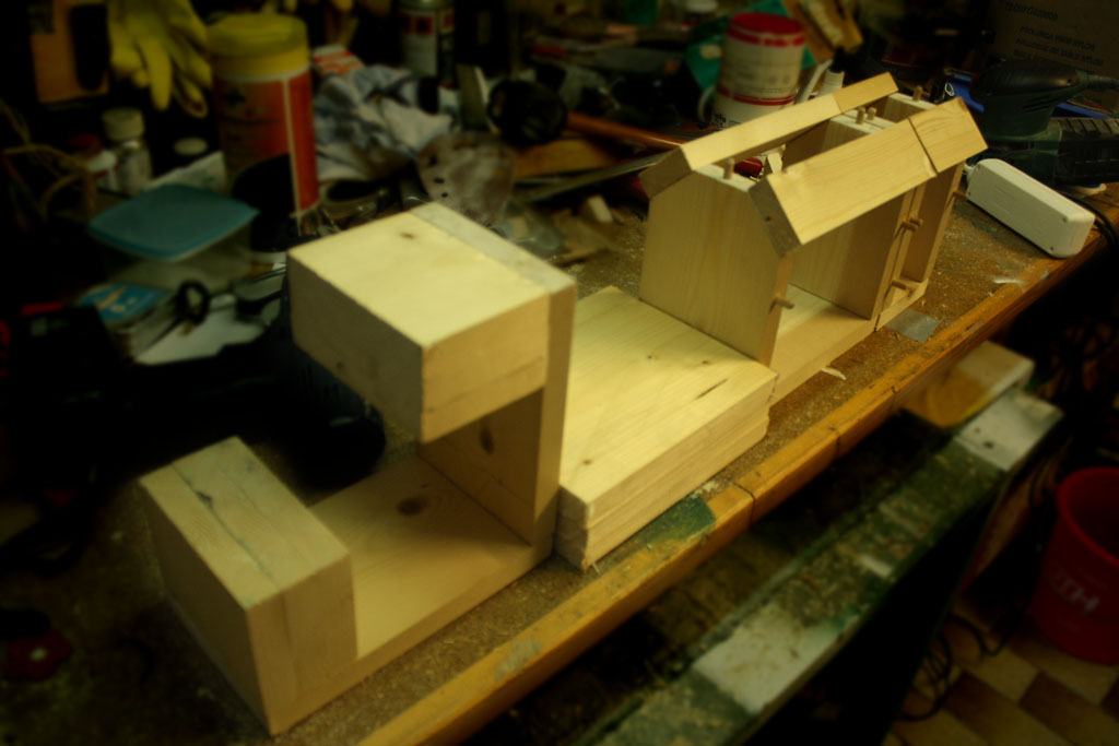
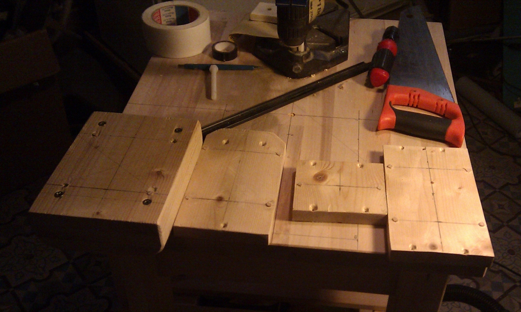
But the issues could be and were overcome with a bit of extra work. Well, a lot of extra work. We sanded down the bad cuts on the 12cm wood. We sanded down the dowels that didn't fit. A few times I had to redrill the dowel holes. But we kept going.
And the pieces started to come together.
The next challenge was cutting the 45° cuts. After some experimenting my SO's father decided to sand those cuts as well using his heavy table sander. I marked the angle and the resultant cut on both sides of the wood, and he sanded it down until the garage was covered in sawdust. But the pieces fit.
With most of the pieces clamped in and more sanding ahead me and my SO took a break and we visited Vienna.
Enter sandman
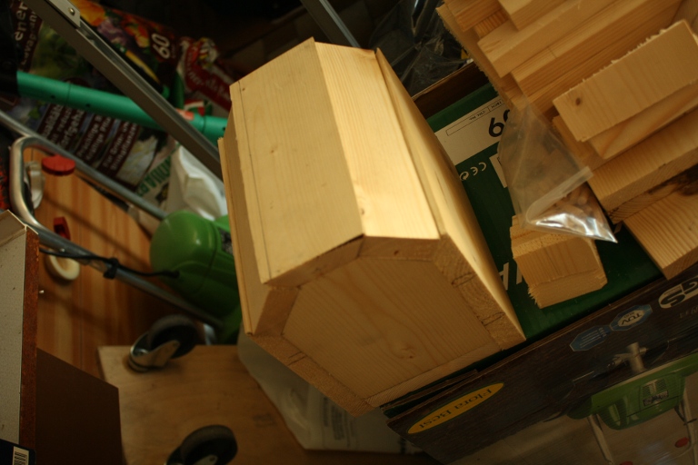
The next part was simple; nothing but sanding. Well, almost nothing. I needed to get new sideplates for the back of the car, a chassis plank and the bolts and pieces for the wheels.
Once all the hardware was bought I used a figure saw to cut the curved plates for the back. The back went into the clamps and that was the last piece to be clamped...
Meanwhile the front modules were sanded, most of that work being done by my SO's father. We used 80 grit bands and the wood literally flew off. We resorted to finer sandpaper for the finishing, naturally. All in all we produced buckets full of sawdust.
Finish?
The sanding took up most of the remaining time before we had to pack and leave. Tired from the hard work my SO's father gave up and left me to it. I also had a feeling that I was in well over my head, but it was with considerable pride that I presented the results.
intermezzo
We returned from the vacation with a tan- well, me with a new skin, really- and not much more. The car arrived much later when my SO's parents drove their car to Belgium for a visit. It was put in the basement, with plans to finish it quickly. That, of course, didn't work out. Many, many other things got in the way.
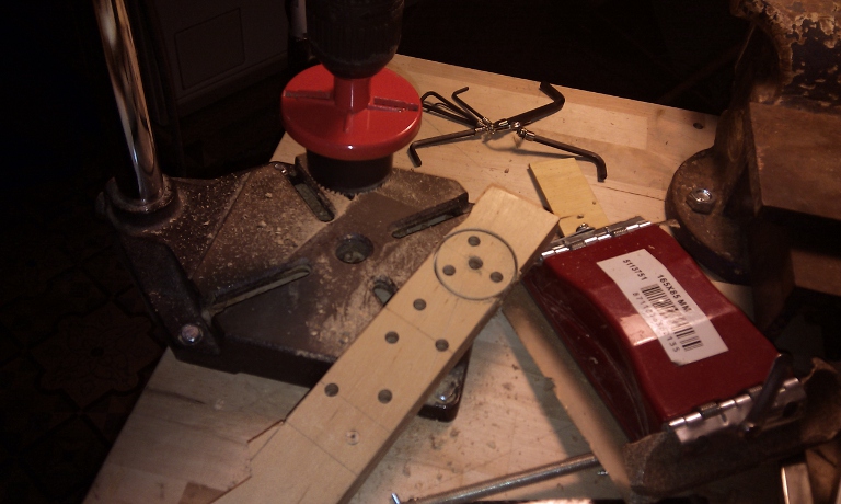
Steering
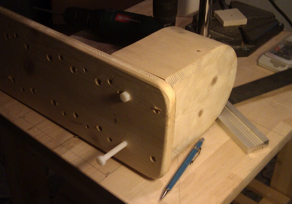
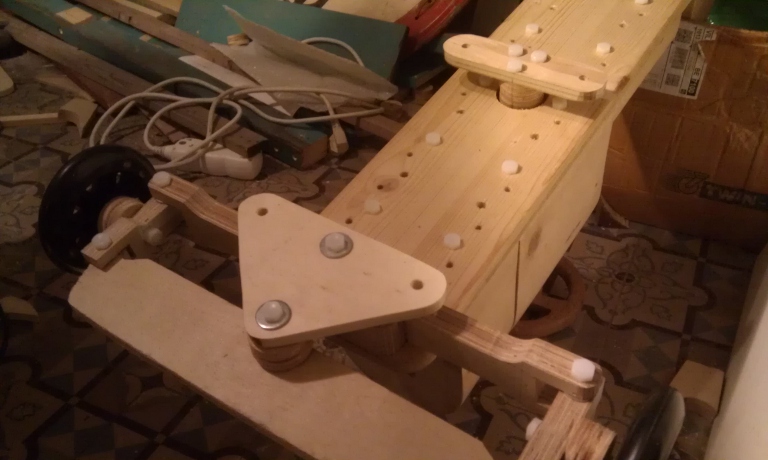
I did find the time to work on the steering mechanism I wanted on the car. In another project I'd gotten nylon bolts in, which I decided were perfect for the car. They also happened to fit the wheels I'd bought. I did a few tests to see how best to mount it, ruined a few axle beams trying to cut straight with my jigsaw (donated by my father in law) and generally mucked about until I finished with the below result.
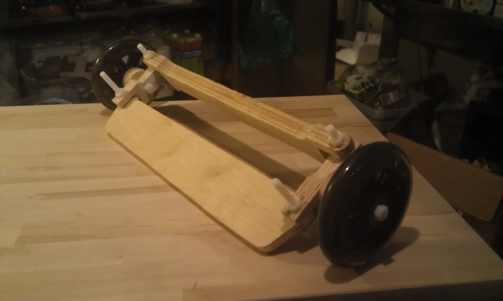
As you can tell there's no 'Ackerman geometry' as I wasn't too sure of how to connect the eventual steering wheel to the steering. There were of course plenty of options depending on the placement of the wheel. And the looking technical/cool factor played, too; why build a car if it looks like a mystery box? I wanted my innerds out! However, after the steering production slowed to a halt. I needed to fit the kid to the car to place the steering wheel. But I knew just a quick sit wouldn't satisfy him, and the dowels were insufficient to keep the modules on for even a short spin around the room.
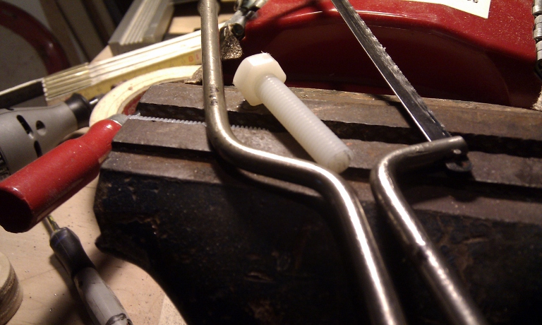
Threads
I had 8mm metric nylon bolts and nuts aplenty and I wanted to use them. This would make it a toy my boy could continue to play with. But how to keep the nut in place? I didn't want to just use metal insert nuts- it would kill the style and double the price of the car. Gluing the nuts in place was not an option either- I needed something mechanically more reliable.
Then, as he so often and perpendicularly does, my friend Fabien came to the rescue. For my birthday he gave me an amazon voucher- something I'd never used. As I happened to be in the market for a ratchet screwdriver I found one- for less than half the price! I decided to look at the entire tool catalog to finish the coupon, and came across a thread cutting set which included m8. Could this be used to cut thread in the wood of the modules themselves?
I bough the set, recieved it a week or so later, and unfortunately had to wait a few months more before I found the time to try it. It worked!
rebirth
In the meantime my firstborn had grown into a cool two-year old and a new son was announced, carried almost to term, and born!
At one point during my parental leave, I decided to put order to the basement. At Ikea I purchased storage shelving and enough plastic boxes to fit all my stuff. It took a mere 6 trips to get everything in! At the mlast moment I decided to splurge on a Bekvam kitchen work bench. Putting everything out, the shelves up, and everything suitably boxed back on the new shelves took a whole month. Parents don't have much free time! So when I told my SO that I wanted to start work on the car- my firstborn having gotten the car 'bug' in the mean time- she told me time was short, and I'd need to take a day off from work to do so. I did.
March 23 2012
As luck would have it the kids were at my parents as their kindergarten was moving, so I'd had a good night's sleep. I was up early, made a coffee and did some computering. I started posting on facebook as a way to motivate myself. My dearest woke, we had a coffee together, and then I dove into the pit for some preparatory cleaning. I cleaned, set up an extra lamp, and loaded my Bekvam with 20 liters of fruit juice to weigh it down. I came back up in time to kiss my SO goodbye as she headed off to work.
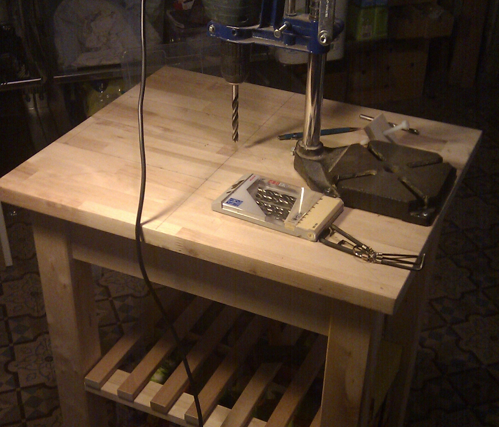
Bekvam
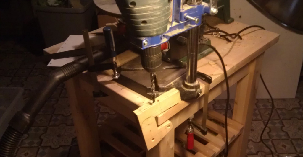
First order of business was to set up the Bekvam workbench. I decided to mount my tools as needed, using 6mm or 8mm hex bolts to fix them. Drilling the holes and putting in insert nuts would take time, but it would pay of later as I switched tools.
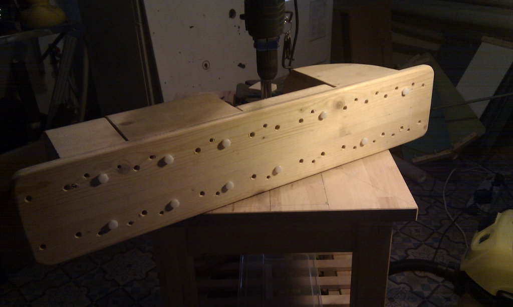
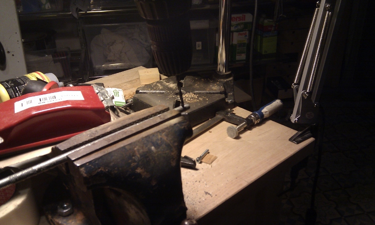
First up was the drill column as I needed to dril holes- a lot of them.
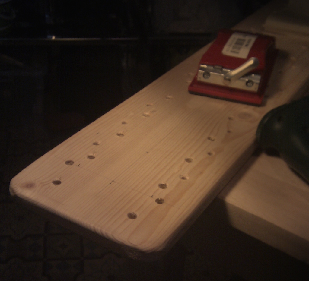
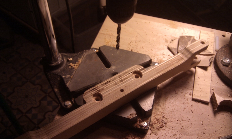
Chassis
With this set up I could redrill the chassis baseboard. It had been set with holes 10cm apart to fit the dowels. But both holes and dowels were badly aligned and needed to go. I was going to replace them with holes for the bolts 8cm apart.
Modules
The holes having been drilled, finished and sanded, I cut the dowels off the modules. To start I unscrewed the bottom parts of the module. I used tape to protect them as I sawed off the dowels close to the base.
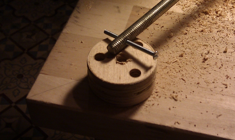
Thread
The next step was to drill the holes for the bolt that were to be threaded. I measured and drilled. Then using only two of the threading drills and an electric hand drill set for screwing, I continued to thread the holes. This took a while as you can imagine.
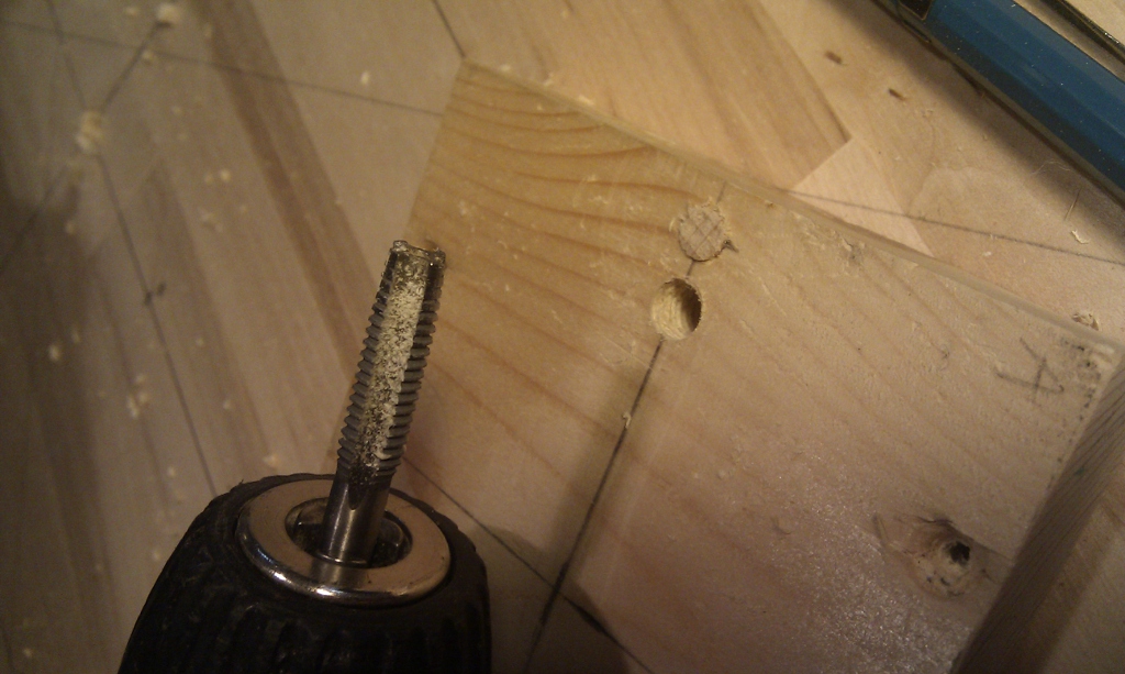
But, most importantly, it worked!.
But it all came together just in time to hop around the block for lunch with my colleague Jan.
Jig
After lunch I started on the rear suspension. I had no idea on how I was going to do it. Without 'springy' wood I could forget about a leaf spring arangement. Shock absorbers were out, too. I finally decided on a complicated- it had to look cool- suspension arm setup that used an elastic for dampening but could be converted to torsion dampening. I found the biggest piece of suitable wood I was willing to sacrifice and drew the biggest arms that fit. Miraculously there was enough for a cool suspension!
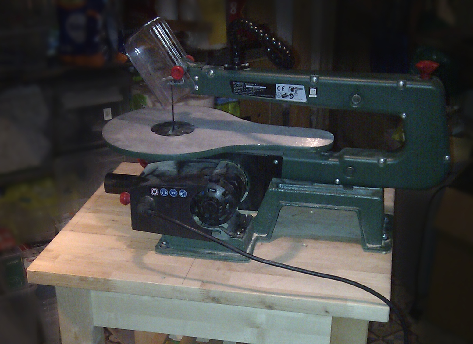
The next step was to set up the jigsaw. This uses 8mm bolts that fit trough elastic holes- not the stablest of setups but I assume there's a reason for that.
Arms
Then it was on to cut the arms! Again I was abusing the poor figuresaw: it wasn't cut out for 22mm plywood. The results never fail to disappoint- but That's what sandpaper is for. One day I'd like to figure out a good way to cut nice straight or curved lines...
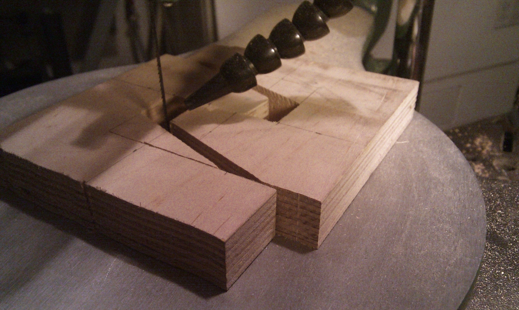
The arms having been cut I continued to drill the needed holes.
And a complete assembly just to take a peak at how it's going to look finished.
Steering wheel
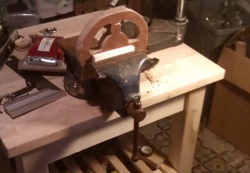
Finally I took some time out to start on the steering wheel. I started with a block of oak that I once cut out of our back door to fit the cat hatch! Old and tough the wood wore out even my electric hacksaw. I couldn't wait for the surprises I'll get when dremeling it into shape. For the steering wheel I had to mount the old bench vise I got on a flea market last year. I even managed to get the belt sander out and start on the smoothing and rounding. Not bad for a day's work...
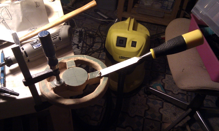
Next up I had to figure out a way to connect the steering wheel to the steering. A rack and pinion? Gears? A belt? Wichever I chose, it'd be a lot more complicated than anything I'd encountered so far. For the moment I had to settle for a passive steering wheel for my boys to hang on to. As it turned out a sleepless night gave me the inspiration needed: a simple push-pull setup. The amount of work needed would be little, the complexity limited- a perfect setup for the end sprint. I happily continued working on the steering wheel, getting some extra sanding cylinders for my dremel.
Diable
One thing I had planned from the beginning was using bigger wheels once the car became too low for my kid. These would need to have hollow, ballbearing axles. An intense yet short search online found the tires closest to 20cm that complied. Push-cart wheels. I even found cheap ones at 25 euro for four, with 15 euros delivery. The only problem was that the axles needed to be 2cm across.
Column
The next day I put Leon on the nearly-finished car to determine where the steering wheel needed to be This enabled me to start planning the steering column.
Axle Pain
There was an aisle with the exact type of wheel I'd bought- and metal pipes to serve as axles. Unfortunately even thoug the axle fit trough the ballbearing, once it was mounted in the wheel the whole thing proved wobbly. There was a 1mm gap on the outside of the axle. My dad offered to look for a piece of pipe to go around the outside, but alas, it's hard to find pipes of exactly 30.6mm.
Mis-Cut
Now I started the work on the steering column. After adding the suspension systems and steering parts I had the two simple metal rods that had originally served as fixed axles. I took the first one, which had glue all over it, to test. I still had 5mm bolts, and decided to drill a 4 mm hole and thread it. This was dodgy with the first hole, but then I accidentally started threading the second hole with a 6mm instead of a 5mm cutter. Since the 8mm rod was threaded itsself, this did not leave enough material for the steering column to be safe
I promptly went downtown and bought a pack of 3mm bolts- using one to fix my oldest' mouth harp. Les excuses sont fait pour s'en servir. Cutting and threading the rod didn't take more than a few five minute sessions spread out over a week
Puckish
Next up were the wooden disks or pucks that would connect to the steering wheel and the rod. The plan was to have the rod permanently stuck trough one of the car's modules, with these disks on top and bottom. Like this the metal rod would never stick out to hurt my kids. I'd have to cut a corresponding hole in the base plank, but this was a minimal adjustment-and might make it look more like a real chassis.
I had loads of wooden disks lying around from the time when I built my subwoofer, and had tried drilling one to fit back when I still wanted to use a 5mm bolt. But drilling a straight hole sideways into a small puck was a bit beyond my setup. I decided to drill the holes in a plank, and drill the pucks out of the plank with my hole saw after.
This worked a charm- although the third puck went awry when the piece skidded. I'd dented the wood with a spike to center the piece, but the dent proved too shallow. Luckily I only needed two pieces right then- though the third would come back to haunt me.
I then drilled the 8 mm holes trough the module- by hand as it wouldn't fit under my press- and inserted the rod. After mounting some spacers I added the pucks and screwed in the bolts that secure them.
This was enough to test the column setup, but it still needed finishing. The 3mm bolts needed to be cut to size. The steering wheel needed to be mated to the top puck and the nylon bolts that connect them likewise cut to size.
It took a while to line up the holes I'd drilled- apparently when drilling pieces that are too small the column doesn't go straight enough. But I finally figured out a combination that worked.
Then I needed to cut a hole in the chassis plank to fit the bottom puck through. Right then my battery drill ran out of juice, but I needed to finish now. After a few painful minutes my hole saw was through, and my work was done. I mounted the module with the steering column and steer and merrily twisted about. Beautiful!
end spurt
I took the car upstairs to see if the steering wheel was at the right height. Naturally my oldest took such a liking to it that my SO insisted it be finished. That night. I guestimated it'd take about two hours. I started at 9pm.
The first thing I needed to do was drill a hole in the front suspension bar to fit the swiveling rod that will do the actual steering. This would need to be exactly between the holes the wheels turn on.
So far, so good. I took the time to sink the holes for the bolts that secure the suspension. This would allow me to have a lower steering mechanism as ground clearance with the small wheels on was rather small.
Then disaster struck. Remember when I cut three pucks and the third one was bad? Now I needed it to add to the bottom of the steering column. I'd glue the steering arm onto this puck, and the puck would be bolted onto the one already attached to the steering column.
However the thinner plyboard I had proved too fragile to cut the pucks. Furthermore the hole saw I'd used to cut the initial pucks cut a lot smaller in the softer wood. Once I had a puck it proved impossible to cut the bolt holes, too- the wood would just tear. All in all I lost close to an hour on this simple part.
After this things sped up, however. I cut the steering arm and the triangular gizmo that would receive it. Then I cut the nylon bolts to size and assembled everything. I had to reassemble the front suspension three times as the hole again did not line up- I need a way to vertically clamp things under my drill press.
But finally everything was ready except for the connection between the steering arms. I decided to cheap out- it was midnight already- and went with extra long zip ties. Done!
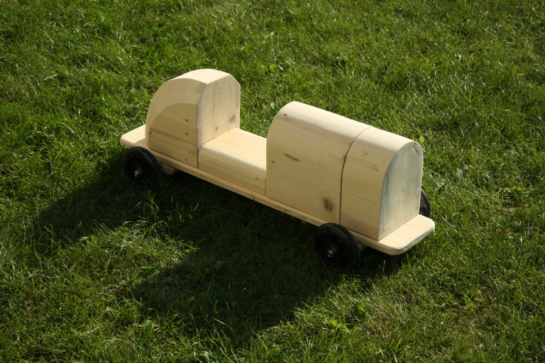
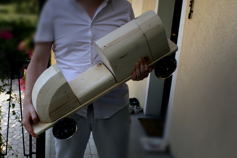
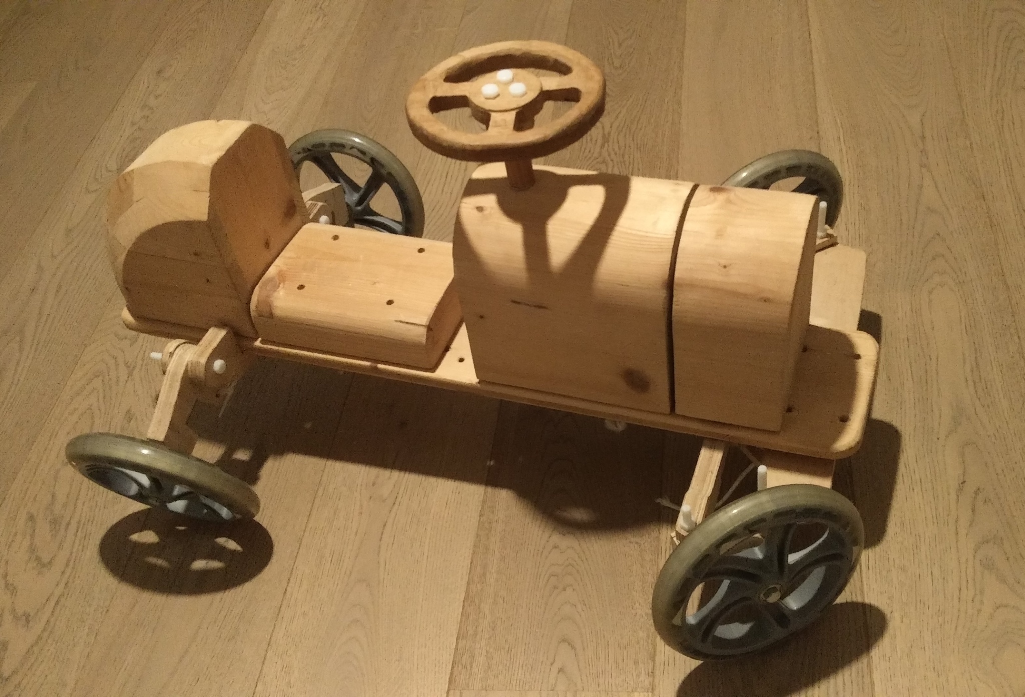
I carried the car up and posed it for a few quicky snapshots, then went to bed satisfied with a job well done.
Trial
In the morning my oldest drank his bottle of milk and jumped on the seat.
I demonstrated the steering action for him, but he became frustrated quickly- it was too hard for him to turn the wheel. I realized I'd have to make the holes in the steering column steering arm closer together- no biggie. After my SO went for a round of the table with him she noticed something was off though. Packing to leave for kindergarten I didn't have time to check, but it seemed the 3mm bolt at the top of the steering column had come loose. Possibly it had even snapped off.
There was nothing to it but go to work and fret all day.
Indeed, when I found the time to check it, the 3mm bolt had snapped off. As a bonus, when I got the puck off, the part that was still sticking out ground a whole swatch of wood away. A few days later I got a chance to pick up 4mm bolts (still having 5mm around in case those would break) and a solid 8mm rod- unthreaded this time so the hole would leave enough metal.
Finished
with the steering done and my kids growing, I decided to take the easy route on the wheels. On holidays in Austria I found 20cm 'scooter' wheels.
These went on easily, in time for oldest to outgrow the lower ones.
Trials with a bungee-cord based suspension were not very successful. The elasticity was too broad, meaning the car was either standing with a negative camber or sitting on its bottom plate.
I ended up using plastic tie straps.
Onwards
more is coming... when I get round to doing it!